Product Overview
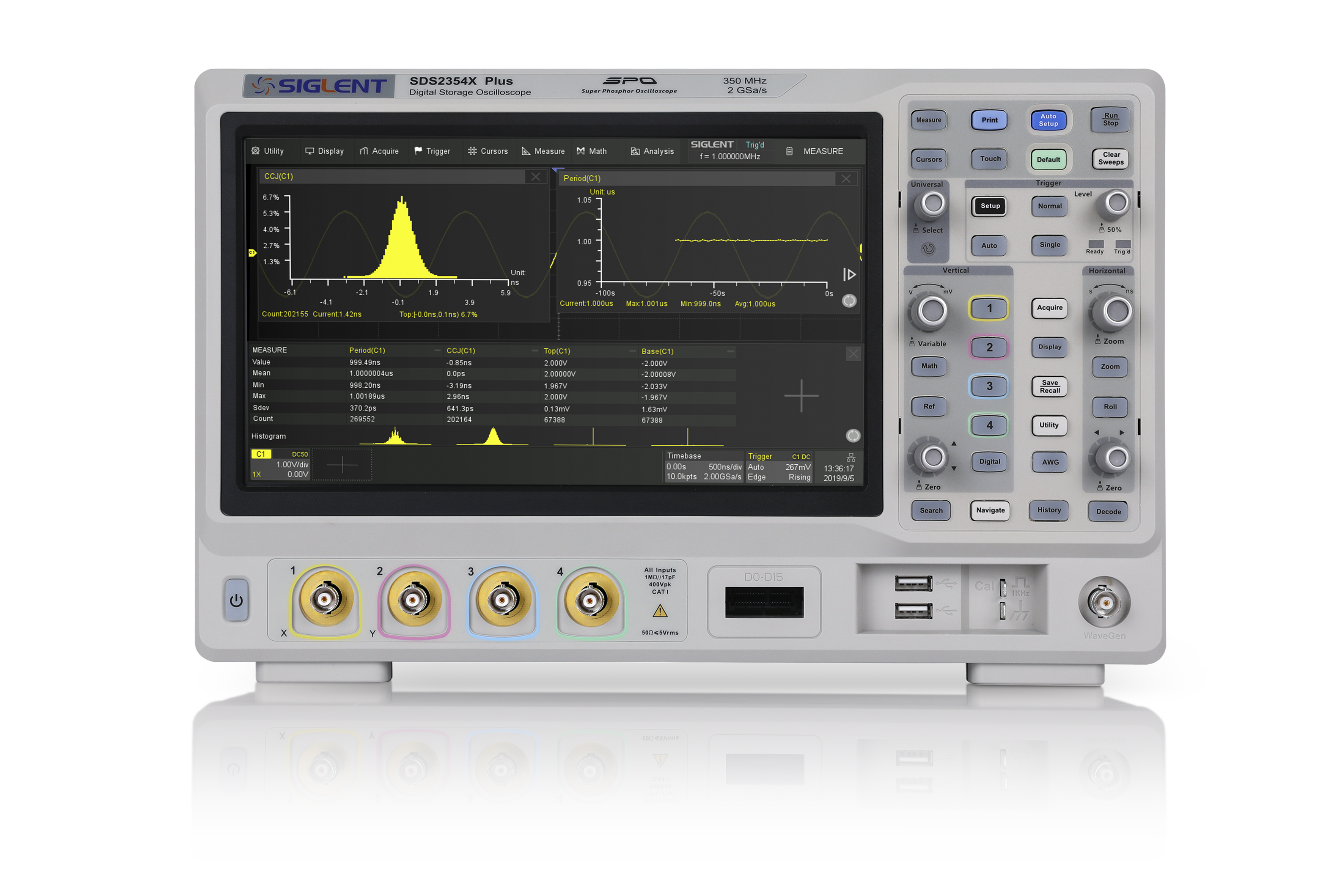
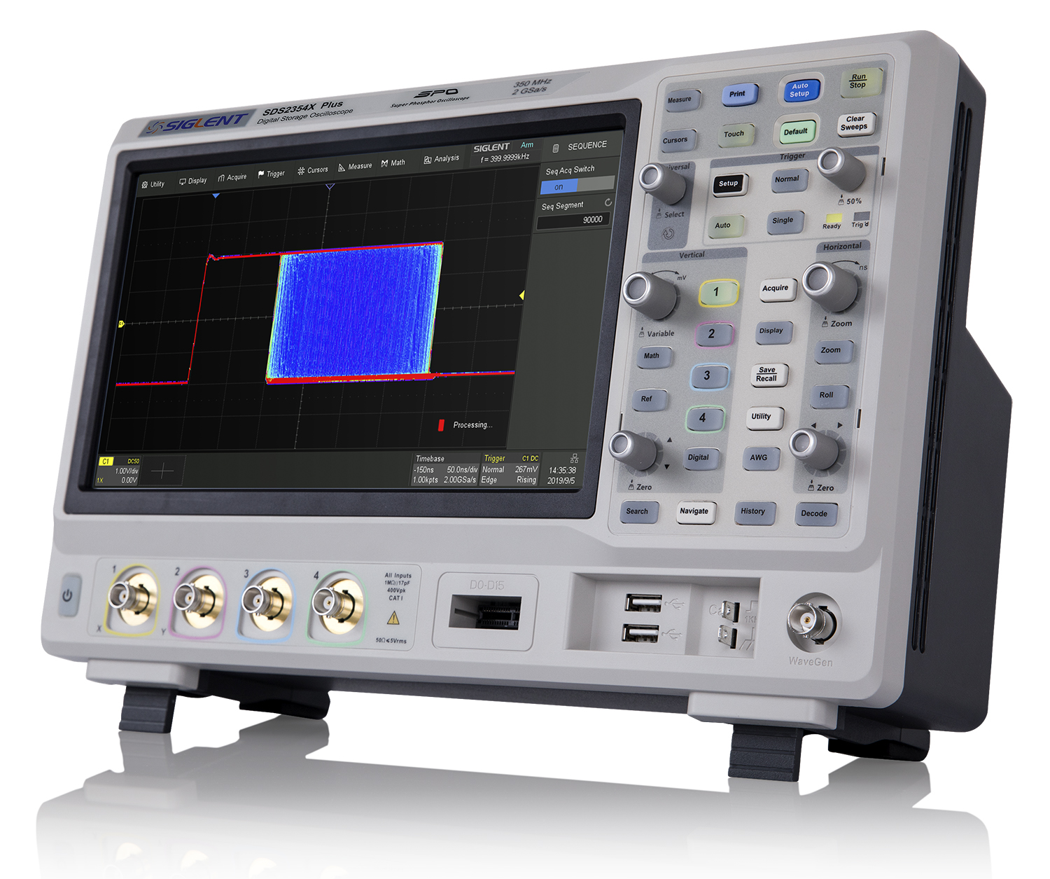
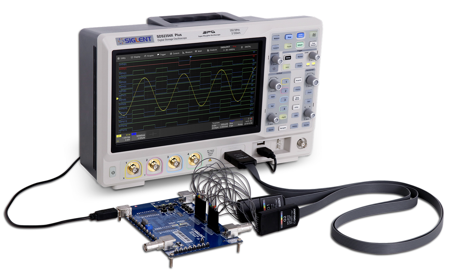
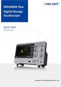
SIGLENT’s SDS2000X Plus series Digital Storage Oscilloscopes are available in bandwidths of 350 MHz, 200 MHz, and 100 MHz, have a maximum sample rate of 2 GSa/s, a maximum record length of 200 Mpts/ch, and up to 4 analog channels + 16 digital channels mixed-signal analysis ability.
The SDS2000X Plus series employs SIGLENT’s SPO technology with a maximum waveform capture rate of up to 120,000 wfm/s (normal mode, up to 500,000 wfm/s in Sequence mode), 256-level intensity grading display function plus a color temperature display mode. It also employs an innovative digital trigger system with high sensitivity and low jitter. The trigger system supports multiple powerful triggering modes including serial bus triggering. History waveform recording, Sequence acquisition, Search and Navigate functions allow for extended waveform records to be captured, stored, and analyzed. An impressive array of measurement and math capabilities, options for a 50 MHz waveform generator, as well as serial decoding, mask test, bode plot, and power analysis are also features of the SDS2000X Plus. A 10-bit acquisition mode helps to satisfy applications that require more than 8-bit resolution.
The large 10.1’’ capacitive touch screen supports multi-touch gestures, while the remote web control, mouse and external keyboard support greatly improve the operating efficiency of the SDS2000X Plus.
Having trouble deciding which scope is right for you?
Click to view a comparison table of our most powerful scopes.
| Bandwidth | Channels | Real time sampling rate | Capture rate | Memory depth | Price | ||
| SDS2354X Plus | 350 MHz | 4+EXT | 2 GSa/s | 120,000 wfm/s | 200 Mpts/ch | €2,599 | Buy Now |
| SDS2204X Plus | 200 MHz | 4+EXT | 2 GSa/s | 120,000 wfm/s | 200 Mpts/ch | €1,899 | Buy Now |
| SDS2104X Plus | 100 MHz | 4+EXT | 2 GSa/s | 120,000 wfm/s | 200 Mpts/ch | €1,199 | Buy Now |
| SDS2102X Plus | 100 MHz | 2+EXT | 2 GSa/s | 120,000 wfm/s | 200 Mpts/ch | €899 | Buy Now |
Key Features
- 350 MHz, 200 MHz, 100 MHz models with real-time sample rate up to 2 GSa/s. A 500 MHz bandwidth upgrade option is available for 350 MHz models.
- SPO technology
- Waveform capture rates up to 120,000 wfm/s (normal mode) and 500,000 wfm/s (sequence mode)
- Supports 256-level intensity grading and color temperature display modes
- Record length up to 200 Mpts/ch, 400 Mpts in total for all 4 channels
- Digital trigger system
- Intelligent trigger: Edge, Slope, Pulse, Window, Runt, Interval, Dropout, Pattern and Video (HDTV supported). Trigger zone helps to simplify advanced triggering
- Serial bus triggering and decoder, supports I2C, SPI, UART, CAN, LIN (Standard) and CAN FD, FlexRay, I2S, and MIL-STD-1553B (optional) protocols
- Low background noise, features 0.5 mV/div to 10 V/div voltage scales
- 10-bit mode provides higher resolution and lower noise
- Segmented acquisition (Sequence) mode, dividing the maximum record length into multiple segments (up to 90,000), according to trigger conditions set by the user, with a very small dead time between segments to capture the qualifying event
- History waveform record (History) function for up to 90,000 triggered waveforms (frames)
- Automatic measurement function on 50+ parameters, supports statistics with histogram and trend
- Two Math traces, support 2 Mpts FFT, +, -, x, ÷, d/dt, ∫dt, √, average, ERES, and formula editor
- Abundant data processing and analysis functions such as Search, Navigate, Mask Test, Bode plot, Power Analysis (optional) and Counter
- 16 digital channels
- Built-in 50 MHz waveform generator (optional)
- Large 10.1” TFT-LCD display with 1024×600 resolution; Capacitive touch screen supports multi-touch gestures
- Multiple interfaces: USB Host, USB Device (USBTMC), LAN(VXI-11/Telnet/Socket), Pass/Fail, Trigger Out
- Built-in web server supports remote control by the LAN port using a web browser; Supports SCPI remote control commands
Product Characteristics
Competitive Front End Performance View more
Competitive Front End Performance
500 MHz bandwidth (at 2 GSa/s sample rate with 500 MHz bandwidth option).

Low noise floor: Only 80 µV rms at 500 MHz bandwidth.
Up to 120,000 wfm/s waveform update rate View more
Up to 120,000 wfm/s waveform update rate
With a waveform update rate of up to 120,000 wfm/s, the oscilloscope can easily capture low-probability events. In Sequence mode the waveform capture rate can reach 500,000 wfm/s.
Record Length of up to 200 Mpts/ch View more
Record Length of up to 200 Mpts/ch
Utilizing a hardware-based Zoom technique and record length up to 200 Mpts, users can select a slower timebase without compromising the sample rate and then quickly zoom in to focus on the area of interest.
10-bit Mode View more
10-bit Mode

10-bit mode combined with Zoom shows you more details and less noise on the waveform.
Multiple Trigger Functions View more
Multiple Trigger Functions
Edge, Slope, Pulse, Video, Windows, Runt, Interval, Dropout, Pattern and serial trigger.
Trigger Zone View more
Trigger Zone
Trigger Zone is available for advanced triggering.
Measurements for All relevant Parameters and Parameter Statistics View more
Measurements for All relevant Parameters and Parameter Statistics


Parameter measurements includes 4 categories: horizontal, vertical, miscellaneous and channel delay providing a total of 50+ different types of measurements. Measurements can be performed within a specified gate period. Measurements on Math, Reference and History frames are supported.
Statistics shows the current value, maximum value, minimum value, standard deviation and mean value of up to 12 parameters simultaneously. Histogram is available to show the probability distribution of a parameter. Trend is available to show the parameter value vs. time.
In addition, horizontal measurements can process up to 1000 signal edges within one single frame, thus greatly improving the test efficiency.
Advanced Math Function View more
Advanced Math Function
Two Math traces, support FFT, +, -, x, ÷, d/dt, ∫dt, √, average, ERES, and formula editor.

Hardware accelerated FFT up to 2 Mpts. This provides high frequency resolution with fast refresh rate. The FFT function also supports a variety of window functions so that it can adapt to different spectrum measurement needs. Three modes (Normal, Average and Max hold) can satisfy different requirements for observing the power spectrum. Auto peak detection and markers are supported.
History Mode View more
History Mode
History function records up to 90,000 triggered waveforms (frames). This is done continuously in the background, so the history waveforms can be played back at any time to find and analyze past events. Serial decode, zoom and cursors measurements can be used.
Sequence Mode View more
Sequence Mode
Segmented memory collection will store the waveform into multiple memory segments (up to 90,000) and each segment will store a triggered waveform together with the dead time information. The interval between segments can be as small as 2 µs. All segments can be played back at an arbitrary framerate using the History function.
Search and Navigate View more
Search and Navigate
The SDS2000X Plus can find events within a record and history based on user specified trigger conditions. Navigate browses through Events flagged by the Search, plays back history frames or continuously moves the delay position on long records (useful in zoom view).
Serial Bus Decode View more
Serial Bus Decode
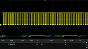
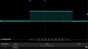
In addition to the decoder lanes correlated to the waveform, bus protocol information can be displayed in tabular form. I2C, SPI, UART, CAN, LIN, CAN FD, FlexRay, I2S and MIL-STD-1553B are supported.
Hardware-based High Speed Mask Test Function View more
Hardware-based High Speed Mask Test Function
The SDS2000X Plus utilizes a hardware-based Mask Test function, performing up to 80,000 Pass / Fail decisions each second. It is easy to generate user defined test templates which the signal trace can be continuously compared to. The failed frames can be automatically stored as history frames or screen shots, making it suitable for long-term signal monitoring or automated production line testing.

Built-in Mask Editor application helps to create custom masks.
Bode Plot View more
Bode Plot
The SDS2000X Plus can control the built-in waveform generator or any stand-alone SIGLENT SDG device to scan the amplitude and phase response over frequency of passive or active circuits. The data is presented as Bode Plot. This makes it possible to replace expensive network analyzers in less demanding applications.
Power Analysis (Optional) View more
Power Analysis (Optional)
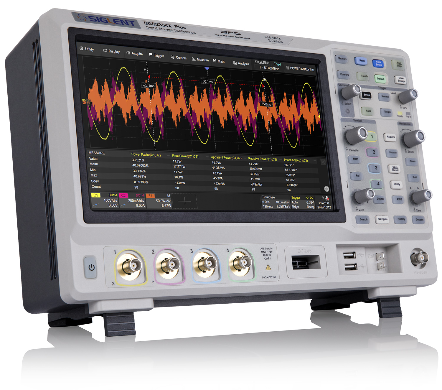
The Power Analysis option provides a full suite of power measurements and analysis, thus improving the efficiency of measurement in switching power supplies and power device designs.
Digital Channels / MSO (Optional) View more
Digital Channels / MSO (Optional)
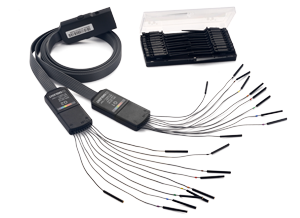
Four analog channels plus 16 digital channels allow the acquisition and triggering of mixed waveforms with one instrument.
50 MHz Built-in Waveform Generator (Optional) View more
50 MHz Built-in Waveform Generator (Optional)
The built-in waveform generator can output waveforms with up to 50 MHz frequency and ±3 V amplitude. Six basic waveforms together with multiple types of predefined waveforms and as user defined arbitrary waveforms are supported.
Complete Connectivity View more
Complete Connectivity
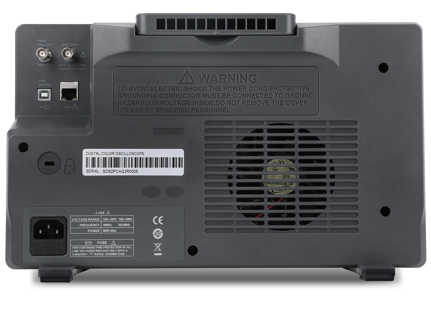
2 x USB Host, 1 x USB Device (USBTMC)
1 x LAN(VXI-11/Telnet/Socket)
1 x Auxiliary Output(Pass/Fail and Trigger Out)
Standard Accessories
Optional Accessories
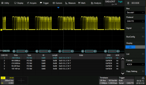
CAN-FD decoding activation license (SDS2000XP series)
CAN FD trigger & decode for the SDS2000XP series oscilloscopes
Learn more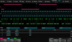
I2S audio decoding activation license (SDS2000XP series)
I2S trigger & decode for the SDS2000XP series oscilloscopes
Learn more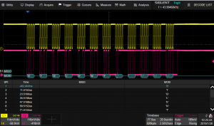
FlexRay decoding activation license (SDS2000XP series)
FlexRay trigger & decode for the SDS5000X series oscilloscopes
Learn more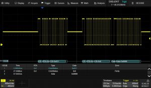
Mil-1553B decoding activation license (SDS2000XP series)
MIL-STD-1553B trigger & decode for the SDS2000XP series oscilloscopes
Learn more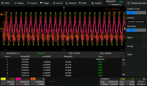
Power Analysis activation license (for the SDS2000XP series)
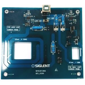
Unlock the power analysis option for the SDS2000XP series of oscilloscopes. Requires a 4 channel SDS2000XP, DF2001A deskew fixture, and at least one current probe for complete functionality.
Learn more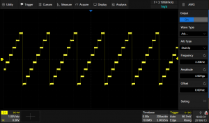
Waveform generator activation license (SDS2000XP series)
Unlocks the built-in function generator control for the SDS2000X Plus series of oscilloscopes.
Learn more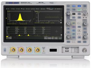
Bandwidth upgrade, 100 to 200 MHz, 4 channel models
100 MHz to 200 MHz bandwidth upgrade (4-ch model) (software)
Learn more
Bandwidth upgrade, 100 to 350 MHz, 2 channel models
100 MHz to 350 MHz bandwidth upgrade (2-ch model) (software)
Learn more
Bandwidth upgrade, 200 to 350 MHz, 4 channel models
200 MHz to 350 MHz bandwidth upgrade (4-ch model) (software)
Learn more
