
Power supply noise differs from ripple, it is another high-frequency component that appears between the output terminals. Noise refers to aperiodic random interference in the power supply output, manifesting as discontinuous and irregular voltage or current spikes. These spikes are often caused by internal and external interference within the system, such as improper circuit design, inadequate wiring, or poor contact.
1 Overview
The power supply is the core of electronic product, delivering a continuous energy to the system. Ripple and noise are critical parameters for evaluating the quality of a power supply, as they reflect the instability and interference in the power supply’s output. Excessive ripple or noise can lead to inefficient operation, system instability, and accelerated equipment aging. Therefore, when designing power modules, it is crucial to accurately measure and assess ripple and noise levels.
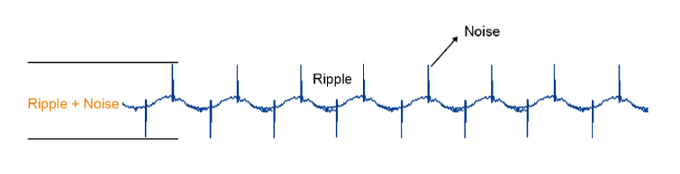
The ripple in a power supply refers to the periodic changes or slight fluctuations in the output that align with the switching frequency. These fluctuations are superimposed on the stable DC signal as an AC component, creating interference. The amplitude of this ripple is typically measured in millivolts (mV). Power supply’s ripple can be caused by various factors, including circuit design details, filter configuration, load variations, and external environmental interference.
Power supply noise differs from ripple, it is another high-frequency component that appears between the output terminals. Noise refers to aperiodic random interference in the power supply output, manifesting as discontinuous and irregular voltage or current spikes. These spikes are often caused by internal and external interference within the system, such as improper circuit design, inadequate wiring, or poor contact.
2 Challenge
In recent years, as power supply voltages continue to decrease, circuit switching speeds increase, chip packages become smaller, and power supply networks grow more complex, the demand for power integrity has risen significantly. Consequently, measuring power supply ripple and noise has become increasingly challenging. We typically use an oscilloscope probe to measure these parameters, as it offers high input impedance, minimizing its impact on the circuit under test, making it an ideal tool for such measurements.
However, because power supply’s noise is typically very low, both the oscilloscope and probe can introduce additional noise during testing. When using a common oscilloscope with a probe, the power supply’s ripple and noise may be obscured by excessive noise floor, or the oscilloscope’s limited offset range may hinder accurate viewing of the test results. To achieve more precise measurements, it is essential to use an oscilloscope with high resolution and an ultra-low noise floor, along with a power rail probe that offers low noise and a high bias range. This combination ensures that the ripple and noise of the power supply are accurately captured.
In addition, the actual testing process involves many operations, and improper handling can introduce interference noise or external electromagnetic interference, thereby reducing measurement accuracy. Therefore, mastering the correct method for measuring ripple and noise is crucial to obtaining reliable results.
3 Reference Solutions
3.1 Oscilloscope
Use a 12-bit high resolution oscilloscope.
There are three types of oscilloscopes on the market: 8-bit, 10-bit, and 12-bit. Of these, the 12-bit oscilloscope offers the highest number of quantization levels (4096) and therefore the smallest quantization error, resulting in more accurate waveform restoration and measurement results. Additionally, a true 12-bit oscilloscope features a front-end amplifier and analog-to-digital converter (ADC) specifically designed for high-resolution applications, providing lower noise, better effective number of bits (ENOB), and improved DC gain accuracy. SIGLEN’s oscilloscope has enhanced resolution mode, which can achieve 16-bit high resolution, making it particularly beneficial for measuring power supply’s ripple and noise.
The basic switching frequency of power conversion devices may be slow, but the edge speed and rise time are fast, which can easily generate high-frequency noise and harmonics. Therefore, users must select an oscilloscope with high bandwidth to effectively diagnose issues related to high-frequency interference. Currently, the bandwidth of SIGLENT’s high-resolution series oscilloscopes ranges from 70 MHz to 4 GHz, offering users a variety of options.
3.2 Probe
Use a Power Rail Probe with high bandwidth, low noise, high input impedance and large DC offset.
In the past, when engineers measured the ripple and noise of power supply, they often used passive probes to directly detect the power and ground network near the chip under test. However, when conventional passive probes are set to a 1x attenuation, the bandwidth is limited to 6 MHz, which is insufficient for accurate measurements. On the other hand, increasing the attenuation to 10x improves bandwidth but significantly increases the oscilloscope’s noise floor, compromising the accuracy of the measurement results. Additionally, to measure ripple or noise on the DC component, engineers traditionally set the oscilloscope to AC coupling mode. However, AC coupling filters out not only the DC component but also low-frequency noise and drift, necessitating the use of a probe with a large vertical offset range for accurate testing.
SIGLENT recommends the SAP4000P power rail probe, specifically designed for testing power supply’s ripple and noise. Its millivolt-level sensitivity enables users to accurately detect noise, ripple, and transient changes in DC power supplies. Additionally, it offers a low-noise solution with a large DC offset, making it ideal for measuring power rail signals.
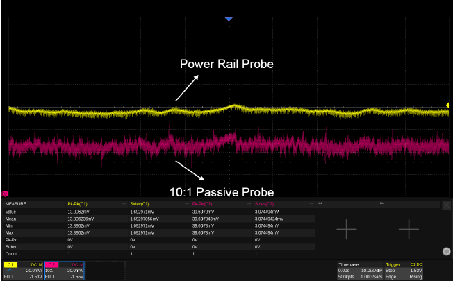
When no DUT is connected and all test conditions are consistent, a noise comparison between the power rail probe and a 10:1 passive probe reveals that the passive probe generates significantly more noise than the power rail probe:
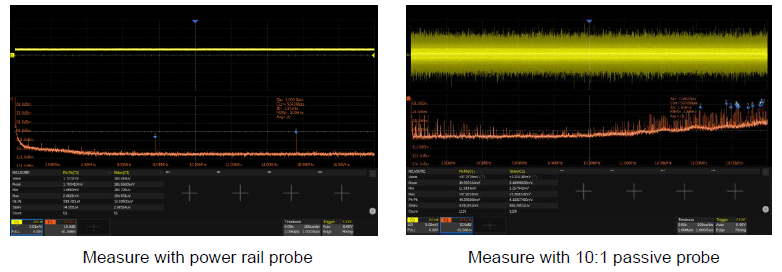
The SAP4000P’s 4 GHz bandwidth and low noise level are instrumental in distinguishing the noise generated by the oscilloscope and probe from the noise and ripple of the DC power supply under test. With a bias setting range of ±24V, the dynamic signal with a DC component can be easily centered on the oscilloscope screen, and the input dynamic range of ±600mV allows for accurate measurement of significant voltage fluctuations. Additionally, the probe’s high impedance of 50kΩ at low frequencies helps eliminate the load effect and minimizes interference from the power supply being tested, while its low impedance of 50Ω at high frequencies ensures proper coaxial cable matching and enhances test bandwidth.
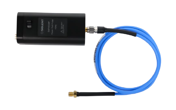
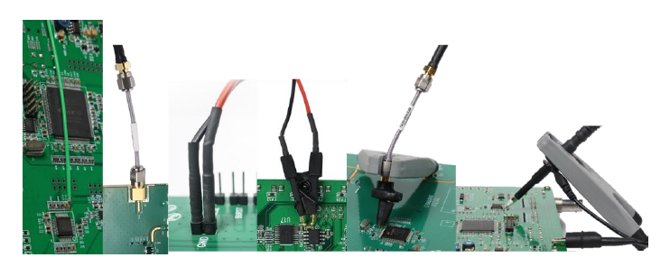
The SAP4000P Power Rail Probe also provides various accessories, such as a double male SMA cable, high-frequency spot probe, and miniature SMD clip. Users can flexibly choose from various test connection methods, including direct cable connection, soldering at the measurement point, and using a passive probe tip point for measurement. These accessories can meet the needs of different application scenarios.
3.3 Points of attention
The bandwidth of the oscilloscope.
The ripple in a power supply is a low-frequency noise, typically ranging from tens to hundreds kHz, which corresponds to the switching frequency. To accurately measure ripple without the interference of high-frequency noise, the oscilloscope’s bandwidth can be limited to 20 MHz. In contrast, power supply’s noise is high-frequency interference, often referring to the AC component superimposed on the output voltage across the oscilloscope’s full bandwidth. Therefore, it’s necessary to utilize the full bandwidth of the oscilloscope for accurate noise measurement.
The vertical scale of oscilloscope.
The lower the vertical scale setting on the oscilloscope, the smaller system’s noise floor. This allows for more precise measurements. To optimize signal observation, adjust the oscilloscope’s vertical scale setting so that the signal waveform occupies 80%-90% of the screen. This setup enhances the oscilloscope’s resolution, making it easier to observe subtle changes in the signal.
The sampling rate of oscilloscope.
To accurately capture waveform details, an oscilloscope should sample 3-5 points, ideally more than 5 points, on the rising edge of the signal of interest. A high sampling rate is crucial, as it minimizes distortion in the test waveform.
The grounding skills of the probe.
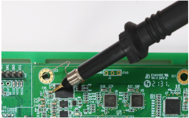
When testing with common passive probes, minimizing noise interference is crucial. To achieve this, the probe’s ground terminal (GND) should be placed as close to the test point as possible, reducing the risk of unnecessary electromagnetic interference (EMI) from a large signal loop. Correct use of the probe’s tip point to touch the test point, combined with grounding using a short spring ground pin, effectively minimizes EMI coupling. Additionally, using auxiliary tools like double-lead adapters or miniature SMD clips enhances testing flexibility and further improves accuracy and convenience.
3.4 Result
When testing the same measurement point on a DUT, such as the filter capacitor on the power pin of DDR3, both a power rail probe and a passive probe can be used. In this scenario, the oscilloscope’s horizontal time scale, vertical scale, and impedance are set identically (with different vertical offsets applied to clearly distinguish the two waveforms, without adjusting the vertical scale until the waveform fills the screen). By selecting standard deviation and peak-to-peak value as measurement parameters, it becomes evident that the signal measured with a common passive probe is overwhelmed by noise. In contrast, the power rail probe can still accurately capture the test results.
3.5 Result Analysis
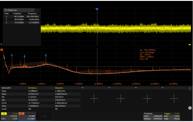
When analyzing power supply’s noise, an oscilloscope can be used to directly observe and measure ripple and noise, allowing for the identification of interference sources. However, as the voltage of digital devices continues to decrease, the complexity of power supply design increases. In some cases, the time-domain waveform alone may not reveal the underlying issues. At this point, converting the time-domain waveform into the frequency domain using FFT (Fast Fourier Transform) can be beneficial. The FFT diagram below shows the main frequency components of the noise, which can help speed up circuit debugging by providing insights from both time-domain and frequency-domain perspectives.
It’s important to note that the effectiveness of FFT varies with the number of test points; more test points result in higher frequency resolution and a clearer FFT outcome. The SDS7000A series oscilloscopes from SIGLENT support up to 32Mpts, offering a peak list display that quickly reveals the amplitude and frequency of key components.
4 Conclusion
This paper outlines key considerations and testing techniques when using SIGLENT’s SAP4000P Power Rail Probe, which features low noise, a large bias range, and high-impedance input, to measure power supply’s ripple and noise. For those looking to assess the impact of these interferences on high-speed signal transmission, SIGLENT’s SDS6000 and SDS7000A series oscilloscopes also support Eye Diagram and Jitter Analysis for further in-depth analysis.